


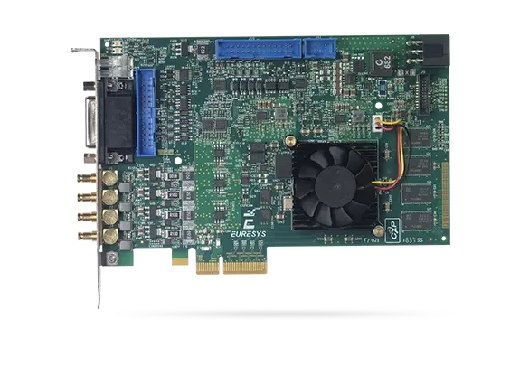
Coaxlink Quad G3
PCIe 3.0 四埠 CoaXPress 影像擷取卡
- 四組 CoaXPress CXP-6 連接埠:2,500 MB/s 攝影機頻寬
- PCIe 3.0(第 3 代)x4 匯流排:3,300 MB/s 匯流排頻寬
- 功能豐富的 20 條數位 I/O 線路
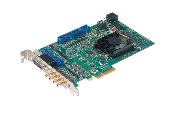
- 風扇散熱式散熱片
- 完善的攝影機控制功能
- Memento 事件記錄工具

PCIe 3.0 (第 3 代) x4 匯流排
3,300 MB/s 的持續匯流排頻寬
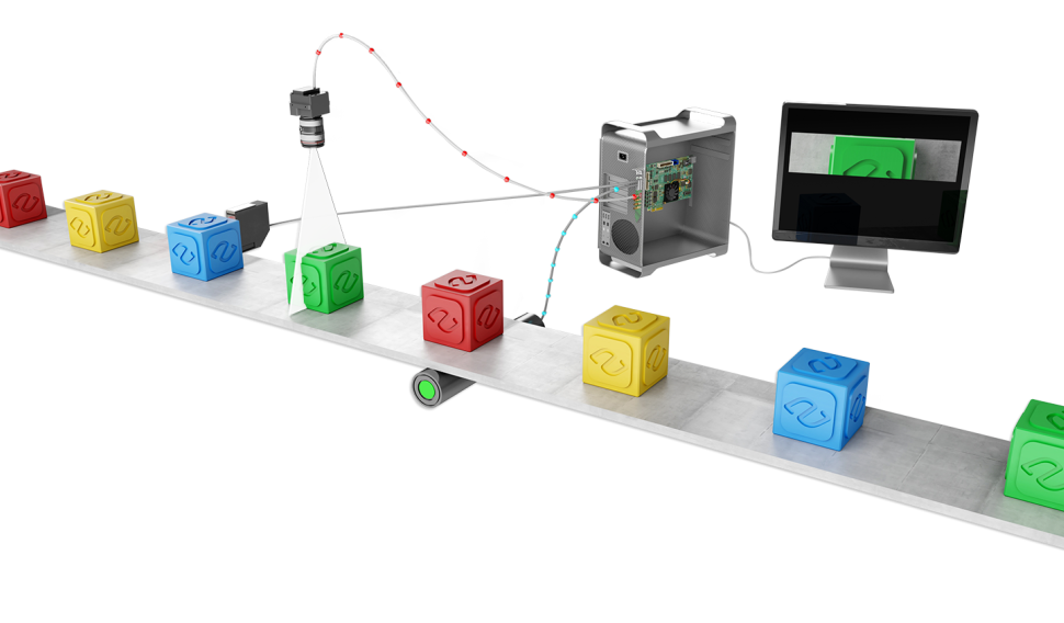
線掃描觸發功能
Allied Vision 的影像擷取卡具備多種功能,可同步線掃描或一維相機、感測器及照明控制器。影像擷取卡能根據從運動編碼器接收的訊號,控制相機的掃描速率。
它們支援連續卷材掃描(用於檢測無限長且持續移動的表面,且不會遺漏任何一條掃描線),以及離散物體掃描(用於擷取在相機前方移動的物體影像)。
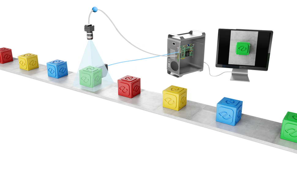
區域掃描觸發功能
Allied Vision 的影像擷取卡具備多種功能,可同步區域掃描或 2D 攝影機、感測器及照明控制器,適用於視野範圍內的靜止或移動物體,或移動中的攝影機。
好處
CoaXPress 供電
-
- 在 24 VDC 供電下,每通道可為您的攝影機提供最高 17 W 的電力,並具備自動裝置偵測、測量及過載保護功能。
- 可進行總電壓與總電流測量,以及各通道的電壓與電流測量,從而進行驗證及監控性能偏差。

長纜線支架
-
- 以 CXP-6 速度(6.25 Gbps)傳輸 40 公尺
- 以 CXP-3 速度(3 Gbps)傳輸 100 公尺
使用標準同軸電纜
-
- 一條經濟實惠的單一線纜,同時實現數據傳輸、相機控制、觸發與電源供應
- 頂尖可靠性與靈活性,於最嚴苛環境中穩定運作
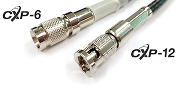
堅固連接器,確保可靠連接
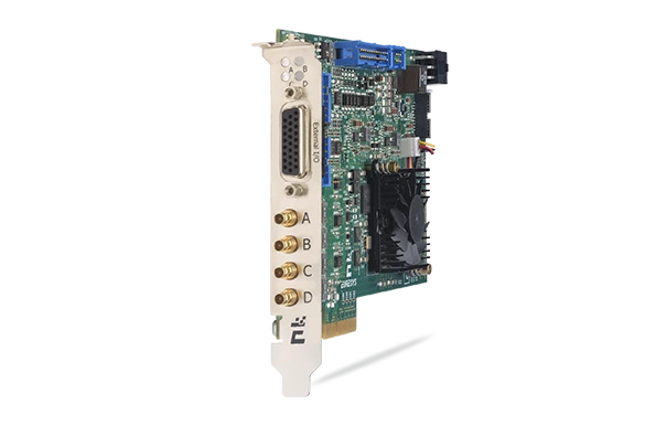
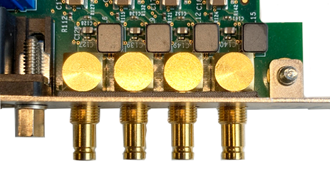
Coaxlink CXP-6 採用 DIN 1.0/2.3 連接器,配備推拉式鎖定系統。
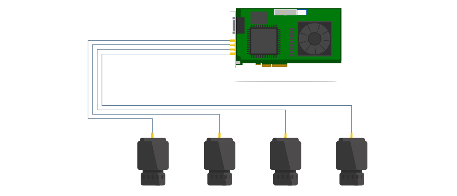
單張同軸鏈接卡最多可連接4台攝影機
單張Coaxlink卡可連接多達4台攝影機
相容於 eGrabber
- eGrabber Studio:eGrabber 的互動式評估與示範應用程式,可存取由 GenTL Producers 提供的 GenICam 功能
- GenTL Console:一款命令列工具,可存取由 Euresys GenTL Producers 所提供的功能與指令

Memento 事件記錄工具
-
- Memento 是一款適用於 Coaxlink 和 Grablink 卡片的高階開發與除錯工具。
- Memento 會精確記錄所有與攝影機、幀擷取卡及其驅動程式,以及應用程式相關的事件日誌。
- 它為開發人員提供帶有時間戳記的事件精確時間軸,並附有上下文資訊和邏輯分析器視圖。
- 它在應用程式開發與除錯期間,以及機器運作期間,皆能提供極具價值的協助。

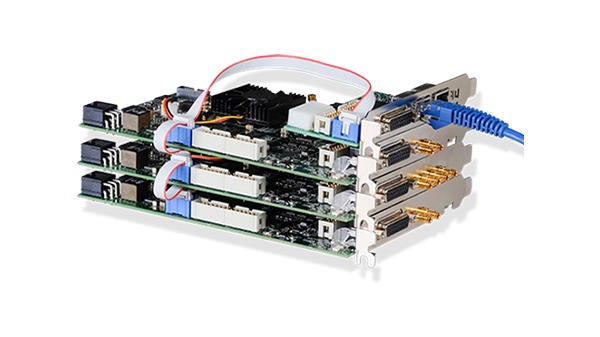
C2C-Link 攝影機同步
允許精確同步多個連接至同一張卡的區域掃描或線掃描相機
-
- 至同一張卡
- 與同一台電腦中的不同卡
- 至不同電腦中的不同卡
符合 GenICam 規範
包含對以下項目的支援:
-
- GenApi
- 標準功能命名規約 (SFNC)
- GenTL

直接 GPU 傳輸
-
- AMD DirectGMA 與 NVIDIA (CUDA) 的範例程式現已提供。
- 直接 GPU 傳輸可消除不必要的系統記憶體複製,降低 CPU 負載並減少延遲,從而顯著提升應用程式的資料傳輸效能。
- 透過AMD DirectGMA技術,可將影像資料直接擷取至GPU記憶體。此功能相容於AMD FirePro W5x00及更高階型號,以及所有AMD FirePro S系列產品。
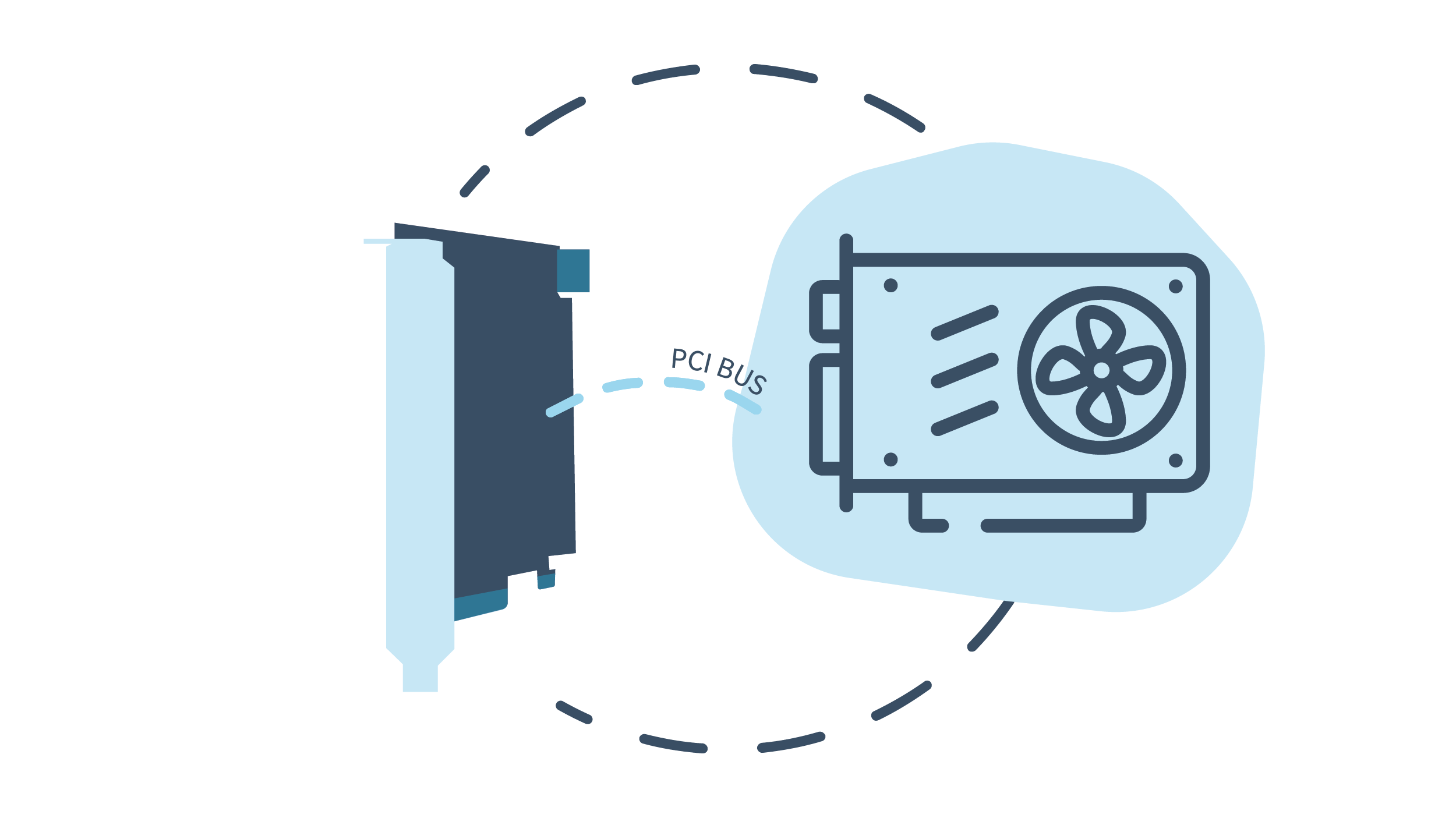
高效能直接記憶體存取(DMA)
-
- 直接轉移至使用者分配的記憶體
- 硬體散射-聚合支援
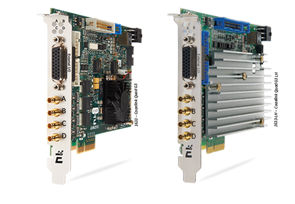
冷卻方式
-
- 風冷散熱器
- 亦可選配被動式(無風扇)散熱器。
Windows、Linux 與 macOS 驅動程式皆可使用
包含對 Intel 64 位元平台以及 ARM 64 位元平台的支援。

通用輸入輸出線
-
- 相容於多種感測器與運動編碼器。
- 高速差動輸入:支援最高 5 MHz 的正交運動編碼器。
- 隔離式電流感測輸入:支援 5V、12V、24V 信號電壓,最高 50 kHz,個別電氣隔離能力達 250VDC 及 170VAC 有效值。
- 隔離式接觸輸出。
- 高速 5V 相容 TTL 輸入/ LVTTL 輸出。
靈活的線掃描相機操作與速率轉換器
-
- 速率轉換器是一款智能可編程的頻率倍增器/分頻器。
- 搭配運動編碼器與線掃描相機使用時,可讓使用者選擇影像中像素的長寬比。
- 它提供了一種校準擷取鏈的方法,可輕鬆實現正方形像素(1:1 寬高比)。
eGrabber
探索我們的幀擷取軟體

General
| Product name: | PC1633 Coaxlink Quad G3 |
| Product code: | 1633 |
| Product status: | Released |
Mechanical
| Form factor: | PCI Express card |
| Format: | Standard profile, half length, 4-lane PCI Express card |
| Cooling method: | Air cooling, fan-cooled heatsink |
| Mounting: | For insertion in a standard height, 4-lane or higher, PCI Express card slot |
| Connectors: | 'A B C D' on card bracket: 4 x DIN 1.0/2.3 75 Ohms coaxial receptacles CoaXPress Host Interface 'EXTERNAL I/O' on card bracket: 26-pin 3-row high-density D-Sub female socket with UNC4-40 jack socket screws I/O lines and I/O power output 'INTERNAL I/O 1' on printed circuit board: 26-pin 2-row 0.1" pitch pin header with shrouding I/O lines and I/O power output 'INTERNAL I/O 2' on printed circuit board: 26-pin 2-row 0.1" pitch pin header with shrouding I/O lines and I/O power output 'C2C-LINK' on printed circuit board: 6-pin 2-row 0.1" pitch pin header with shrouding Card-to-card link 'AUXILIARY POWER INPUT' on printed circuit board: 6-pin PEG power socket 12 V DC power input for PoCXP and I/O power output |
| LED indicators: | 'A', 'B', 'C', 'D' on bracket: Bi-color red/green LEDs CoaXPress Host connector indicator 'FPGA STATUS LAMP' on PCB: Bi-color red/green LED FPGA status indicator 'BOARD STATUS LAMP' on PCB: Bi-color red/green LED Board status indicator |
| Switches: | 'RECOVERY' on PCB: 3-pin 1-row 0.1" header or 2-way DIP switch Firmware emergency recovery |
| Dimensions: | PCB L x H: 167.65 mm x 111.15 mm [6.6 in x 4.38 in] |
| Weight: | Net weight: 173 g [6.1 oz] Gross weight: 274 g [9.7 oz] |
Host Bus
| Standard: | PCI Express 3.0 |
| Link width: | 4 lanes 1 lane or 2 lanes with reduced performance |
| Link speed: | 8.0 GT/s (PCIe 3.0) 5.0 GT/s (PCIe 2.0) with reduced performance |
| Maximum payload size: | 512 bytes |
| DMA: | 32- and 64-bit |
| Peak delivery bandwidth: | 3,900 MB/s |
| Effective (sustained) delivery bandwidth: | 3,350 MB/s (Host PC motherboard dependent) |
| Power consumption: | Typ. 16.8 W (3.8 W @ +3.3V, 13 W @ +12V), excluding camera and I/O power output |
Camera Inputs
| Camera interface standard: | CoaXPress |
| Interface standard(s): | CoaXPress 1.0, 1.1, 1.1.1, 2.0 and 2.1 |
| Maximum link speed: | CXP-6 |
| Maximum link width: | 4 connections |
| Camera powering: | PoCXP |
| Connectors: | Four DIN1.0/2.3 75 Ohms CXP-6 |
| Status LEDs: | One CoaXPress Host connection status LED per connection |
| Number of cameras: | Area-scan cameras: One 1- or 2- or 4-connection camera One 1- or 2- or 4-connection multi-stream camera (up to 4 data streams) One or two 1- or 2-connection cameras One 1- or 2-connection and one or two 1-connection cameras Up to four 1-connection cameras One 4-connection sub-link of an 8-connection camera Line-scan cameras: One 1- or 2- or 4-connection camera One or two 1- or 2-connection cameras Up to four 1-connection cameras |
| Maximum number of cameras: | 4 |
| Line-scan cameras supported: | Yes |
| Maximum aggregated camera data transfer rate: | 25 Gbps (2,500 MB/s) |
| Supported CXP down-connection speeds: | 1.25 Gbps (CXP-1), 2.5 Gbps (CXP-2), 3.125 Gbps (CXP-3), 5 Gbps (CXP-5), and 6.25 Gbps (CXP-6) |
| Number of CXP data streams (per camera): | 4 on '1-camera, 4 data-stream' firmware variant 1 per camera on other firmware variants |
| Maximum CXP stream packet size: | 16,384 bytes |
| PoCXP (Power over CoaXPress): | PoCXP Safe Power: 17 W of 24V DC regulated power per CoaXPress connector PoCXP Device detection and automatic power-on Overload and short-circuit protections On-board 12V to 24V DC/DC converter A +12V power source must be connected to the AUXILIARY POWER INPUT connector using a 6-pin PEG cable |
| Camera types: | Area-scan cameras: Grayscale and color (YCbCr, YUV, RGB and Bayer CFA) Single-tap (1X-1Y) progressive-scan Line-scan cameras and contact imaging sensors: Grayscale and color RGB |
| Camera pixel formats supported: | Mono8, Mono10, Mono12, Mono14, Mono16 BayerXX8, BayerXX10, BayerXX12, BayerXX14, BayerXX16 where XX = GR, RG, GB, or BG RGB8, RGB10, RGB12, RGB14, RGB16 RGBA8, RGBA10, RGBA12, RGBA14, RGBA16 YCbCr601_422_8, YCbCr601_422_10 YCbCr709_422_8, YCbCr709_422_10 YUV422_8, YUV422_10 Raw |
Area Scan Camera Control
| Trigger: | Precise control of asynchronous reset cameras, with exposure control. Support of camera exposure/readout overlap. Support of external hardware trigger, with optional delay and trigger decimation. |
| Strobe: | Accurate control of the strobe position for strobed light sources. Support of early and late strobe pulses. |
Line Scan Camera Control
| Scan/page trigger: | Precise control of start-of-scan and end-of-scan triggers. Support of external hardware trigger, with optional delay. Support of infinite acquisition, without missing line, for web inspection applications. |
| Line trigger: | Support for quadrature motion encoders, with programmable noise filters, selection of acquisition direction and backward motion compensation. Rate Converter tool for fine control of the pixel aspect ratio: Rate Conversion Ratio in the range 0.001 to 1000 with an accuracy better than 0.1%. Rate Divider tool |
| Line strobe: | Accurate control of the strobe position for strobed light sources. |
On-Board Processing
| On-board memory: | 1 GB |
| Image data stream processing: | Unpacking of 10-/12-/14-bit to 16-bit with selectable justification to LSb or MSb Optional swap of R and B components Little endian conversion |
| Flat-field correction: | Only available with the '1-camera' and '1-camera, line-scan' firmware variants |
| Input LUT (Lookup Table): | Available on all the firmware variants but '1-camera, 4-data-stream': Monochrome 8-bit to 8-bit transformation Monochrome 10-bit to 8-, 10- or 16-bit transformations Monochrome 12-bit to 8-, 12- or 16-bit transformations |
| Bayer CFA to RGB decoder: | '1-camera' firmware variant: 3x3 linear interpolation method 3x3 median-based interpolation method '2-camera' firmware variant: 5x5 gradient-based interpolation method (for one camera only) |
| Data stream statistics: | Measurement of: Frame rate (Area-scan only) Line rate Data rate Configurable averaging interval |
| Event signaling and counting: | The application software can be notified of the occurrence of various events: Standard event: the EVENT_NEW_BUFFER event notifies the application of newly filled buffers A large set of custom events Custom events sources: I/O Toolbox events Camera and Illumination control events CoaXPress data stream events CoaXPress host interface events Each custom event is associated with a 32-bit counter that counts the number of occurrences The last three 32-bit context data words of the event context data can be configured with event-specific context data: Event-specific data State of all System I/O lines sampled at the event occurrence time Value of any event counter |
General Purpose I/O
| Number of lines: | 20 I/O lines: 4 differential inputs (DIN) 4 singled-ended TTL inputs/outputs (TTLIO) 8 isolated inputs (IIN) 4 isolated outputs (IOUT) |
| Usage: | Any I/O input lines can be used by any LIN tool of the I/O Toolbox Selected pairs of I/O input lines can be used by any QDC tool of the I/O toolbox to decode A/B signals of a motion encoder |
| Electrical specifications: | DIN: High-speed differential inputs, up to 5 MHz, compatible with ANSI/EIA/TIA-422/485 differential line drivers and complementary TTL drivers TTLIO: High-speed 5V-compliant TTL inputs or LVTTL outputs, compatible with totem-pole LVTTL, TTL, 5V CMOS drivers or LVTTL, TTL, 3V CMOS receivers IIN: Isolated current-sense inputs with wide voltage input range up to 30V, compatible with totem-pole LVTTL, TTL, 5V CMOS drivers, RS-422 differential line drivers, potential free contacts, solid-state relays and opto-couplers IOUT: Isolated contact outputs compatible with 30V / 100mA loads NOTE: IIN and IOUT lines provide a functional isolation grade for the circuit technical protection. It does not provide an isolation that can protect a human being from electrical shock! |
| Filter control: | Glitch removal filter available on all System I/O input lines Configurable filter delay: Custom value Fixed values for DIN and TTLIO lines: 50 ns, 100 ns, 200 ns, 500 ns, 1 µs Fixed values for IIN lines: 500 ns, 1 µs, 2 µs, 5 µs, 10 µs |
| Polarity control: | Yes |
| Power output: | Non-isolated, +12V, 1A, with electronic fuse protection |
| I/O Toolbox tools: | The I/O Toolbox is a configurable interconnection of tools that generates events (usually triggers): Line Input tool (LIN): edge detector delivering events on rising or falling edges of any selected input line. Quadrature Decoder tool (QDC): a composite tool including: A quadrature edge detector delivering events on selected transitions of selected pairs of input lines. An optional backward motion compensator for clean line-scan image acquisition when the motion is unstable. A 32-bit up/down counter for delivering a position value. Device Link Trigger tool (DLT): delivers an event on reception of a valid high-speed CoaXPress 2.0 connection trigger packet message from the remote device. User Actions Scheduler tool (UAS): to delegate the execution of 'User Actions' at a scheduled time or encoder position. Possible user actions include setting low/high/toggle any bit of the User Output Register or generation of any User Events. Delay tool (DEL): to delay up to 16 events from one or two I/O toolbox event sources, by a programmable time or number of motion encoder ticks (any QDC events). Divider tool (DIV): to generate an event every nth input events from any I/O toolbox event source. Multiplier/divider tool (MDV): to generate m events every d input events from any I/O toolbox event source. The 'Input Tools' (LIN, QDC, DLT and UAS) can be further processed by the 'Event Tools' (DEL, DIV and MDV) to generate any of the following "trigger" events: The "cycle trigger" of the Camera and Illumination controller The "cycle sequence trigger" of the Camera and Illumination controller The "start-of-scan trigger" of the Acquisition Controller (line-scan only) The "end-of-scan trigger" of the Acquisition Controller (line-scan only) |
| I/O Toolbox composition: | Determined by the selected firmware variant: '1-camera': 8 LIN, 1 QDC, 1 UAS, 2 DEL, 1 DIV, 1 MDV, 2 C2C '2-camera': 8 LIN, 2 QDC, 1 UAS, 2 DEL, 2 DIV, 2 MDV, 2 C2C '3-camera': 8 LIN, 2 QDC, 1 UAS, 2 DEL, 2 DIV, 2 MDV, 2 C2C '4-camera': 8 LIN, 4 QDC, 1 UAS, 4 DEL, 4 DIV, 4 MDV, 2 C2C '1-camera, 4-data-stream': 8 LIN, 1 QDC, 1 UAS, 2 DEL, 1 DIV, 1 MDV, 2 C2C '1-camera, line-scan': 8 LIN, 1 QDC, 1 UAS, 2 DEL, 1 DIV, 1 MDV, 3 C2C '2-camera, line-scan': 8 LIN, 2 QDC, 1 UAS, 2 DEL, 2 DIV, 2 MDV, 3 C2C '4-camera, line-scan': 8 LIN, 4 QDC, 1 UAS, 4 DEL, 4 DIV, 4 MDV, 3 C2C '1-slm-camera': 8 LIN, 1 QDC, 1 UAS, 2 DEL, 1 DIV, 1 MDV, 3 C2C '1-sls-camera': 8 LIN, 1 QDC, 1 UAS, 2 DEL, 1 DIV, 1 MDV, 3 C2C |
C2C Link
| Description: | Accurate synchronization of the trigger and the start-of-exposure of multiple grabber-controlled area-scan cameras. Accurate synchronization of the start-of-cycle, start-of-scan and end-of-scan of multiple grabber-controlled line-scan cameras. |
| Specification: | C2C-Link synchronizes cameras connected to: the same card to different cards in the same PC (requires an accessory cable such as the "3303 C2C-Link Ribbon Cable" or a custom-made C2C-Link cable) to different cards in different PCs (requires one "1636 InterPC C2C-Link Adapter" for each PC and one RJ 45 CAT 5 STP straight LAN cable for each adapter but the last one) Maximum distance: 120 cm inside a PC 1200 m cumulated adapter to adapter cable length Maximum trigger rate: 2.5 MHz for configurations using a single PC, or up to 10 PCs and 100 m total C2C-Link cable length 200 kHz for configurations up to 32 PCs and 1200m total C2C-Link cable length Trigger propagation delay from master to slave devices: Less than 10 ns for cameras on the same card or on different cards in the same PC Less than 265 ns for cameras on different cards in different PCs (3 PCs and 40m total C2C-Link cable length) |
Software
| Driver name: | eGrabber |
| First release: | Coaxlink 4.0 |
| Current release: | eGrabber 25.12 |
| Host PC Operating System: | Microsoft Windows 11, 10 for x86-64 (64-bit) processor architecture Linux for x86-64 (64-bit) and AArch64 (64-bit) processor architectures macOS for x86-64 (64-bit) and AArch64 (64-bit) processor architectures |
| APIs: | EGrabber class, with C++ and .NET APIs: .NET assembly designed to be used with development environments compatible with .NET frameworks version 4.6 or higher GenICam GenTL producer libraries compatible with C/C++ compilers: 'x86_64' dynamic library designed to be used with ISO-compliant C/C++ compilers for the development of x86-64 (64-bit) applications 'aarch64' dynamic library designed to be used with ISO-compliant C/C++ compilers for the development of AArch64 (64-bit) applications |
| Memento supported: | Yes |
Environmental
| Operating ambient air temperature: | 0°C to +55°C / +32°F to +131°F |
| Operating ambient air humidity: | 10% to 90% RH non-condensing |
| Storage ambient air temperature: | -20°C to +70°C/ -4°F to +158°F |
| Storage ambient air humidity: | 10% to 90% RH non-condensing |
Certifications
EMC standards
-
European Council EMC Directive 2014/30/EU
United States FCC CFR Title 47 Part 15B
- EMC - Emission
-
EN 55032:2015 / CISPR 32:2012 Class B
FCC CFR Title 47 Part 15B Class B
- EMC - Immunity
-
EN 55024:2010 / CISPR 24:2010
EN 61000-4-2:2009
EN 61000-4-3:2006
EN 61000-4-4:2004
EN 61000-4-6:2014
- KC Certification
-
Korean Radio Waves Act, Article 58-2, Clause 3
- Flammability
-
PCB compliant with UL 94 V-0
- RoHS
-
European Union Directive 2015/863 (ROHS3)
- REACH
-
European Union Regulation 1907/2006
- WEEE
-
Must be disposed of separately from normal household waste and must be recycled according to local regulations